RasuunDrive® UHV 19mm – Type 3
The RasuunDrive® UHV 19mm – type 3 is using Braycote 601 EF for lubrication as it is espacially designed for applications in ultrahigh-vacuum environments. It offers a travel range of 25.5 mm and
is driven by a stepper motor with 200 steps per rotation in an open loop control. Directly connected to the motor is a low-backlash CoograDrive® gear with a reduction ratio of 40:1 by means of
which a dry-lubricated ball-screw drive with a pitch of 0.5 mm is driven.
Benefits
1) Vacuum suitable lubrication
2) Use of high quality materials
3) High axial load capacity
4) Robust control without feedback system
5) Adapter with cylindrical surface
Technical parameters
The values shown are based on calculations and measurement procedures carried out by Micromotion GmbH, which are carried out according to the current state of the art. Our definitions can be found at www.micromotion-drives.com. For further information please contact sales@micromotion.de.
Nr.
Parameter
Symbol
Value
Properties
P-001
Vacuum suitable
Ultrahochvakuum
P-003
Ratio
i
40 : 1
P-004
Self-locking
ja
P-005
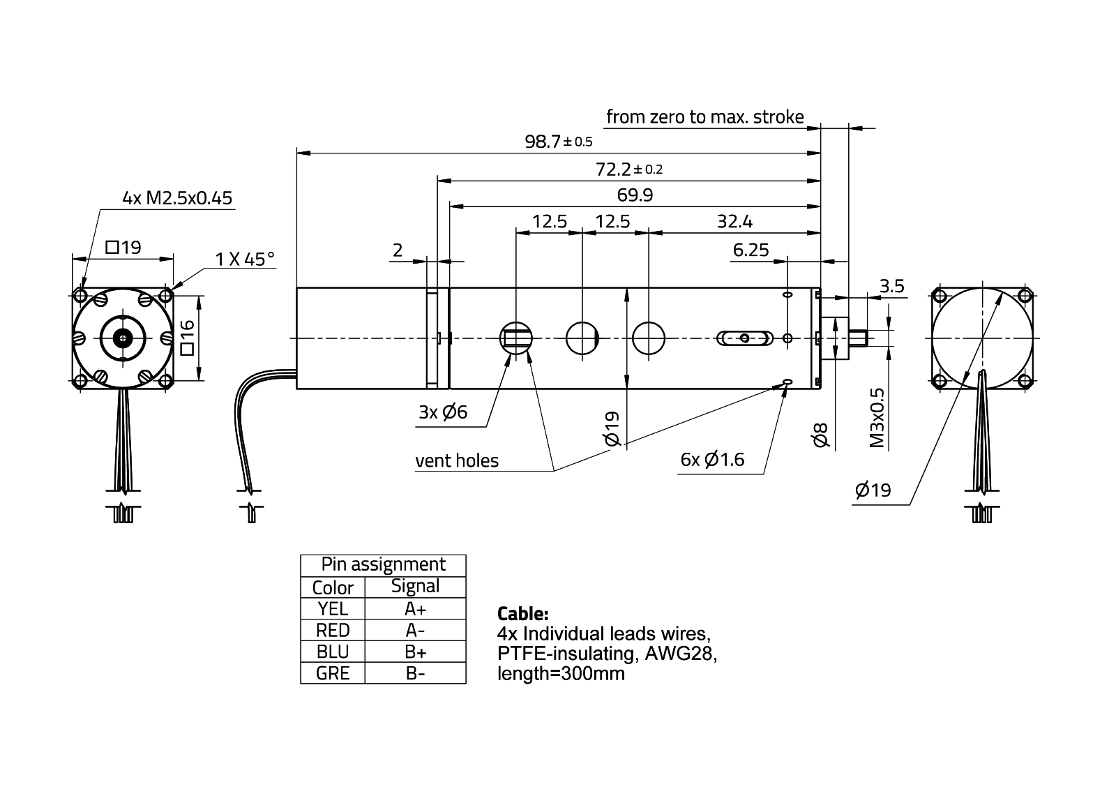
Travel range
s
25.5 mm
P-008
Repeatability unidirectional
0.75 μm
P-009
Repeatability bidirectional
3 μm
P-010
Accuracy
20 μm
P-012
Resolution
0.0625 μm
P-014
Lost motion
7.5 μm
P-015
Backlash
0.01 μm
P-016
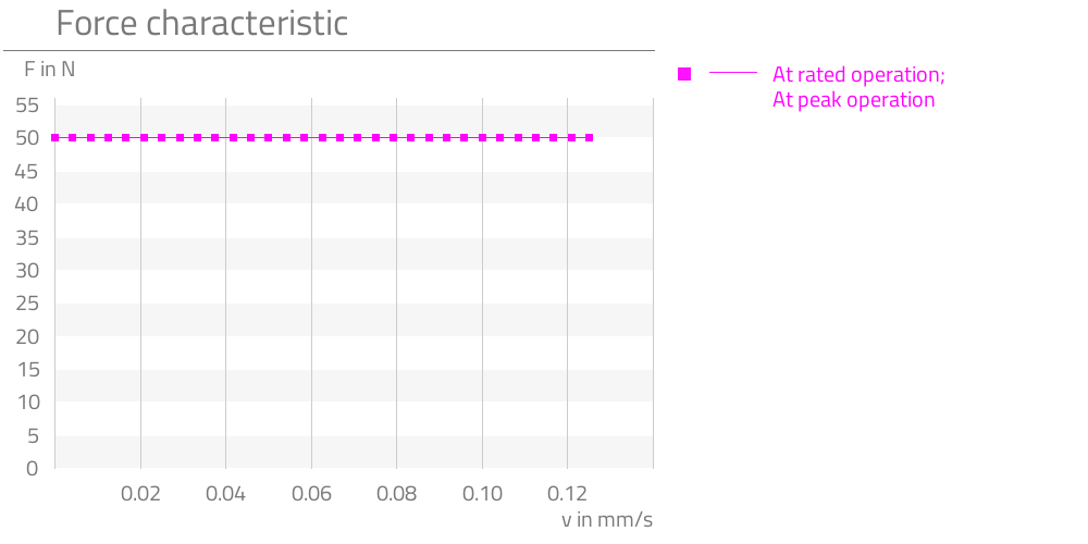
Rated force
F
50 N
P-017
Peak force
F
50 N
P-018
Momentary peak force
F
50 N
P-023
Rated speed
v
0.20833 mm/s
P-024
Maximum speed
v
0.20833 mm/s
P-034
Lifetime for rated operation
300 h
P-035
Radial backlash output shaft
0 μm
P-036
Axial backlash output shaft
0 μm
P-044
Max. axial load on output shaft (non-operating, impulsive load)
F
50 N
P-055
Moment of inertia
I
900038 * 10-4 gcm2
P-057
Min. permissible ambient temperature (non-operating)
T
-20 °C
P-058
Min. permissible ambient temperature (operating)
T
-10 °C
P-059
Max. permissible ambient temperature (non-operating)
T
150 °C
P-060
Max. permissible ambient temperature (operating)
T
120 °C
Motor data: Stepper VSS 19.200.0,6-UHVG-2g5-BC-R
P-100
Motortype
Stepper
P-102
Maximum speed of motor
n
1000 rpm
P-105
Holding torque of motor (unpowered)
T
0.9 mNm
P-109
Rated current of motor
I
600 mA
P-111
Rated voltage of motor
U
42 V
P-112
Phase resistance of motor
R
2.1 ohm
P-113
Inductance of motor
L
0.85 mH
P-115
Full step angle of motor
1.8 °
P-116
Angular accuracy of step of motor
±0.09 °
P-117
Electrical time constant of motor
t
0.367 ms
P-118
Max. coil temperature of motor
T
300 °C
Data limit switch
P-302
Configuration Limit switches
no limit switches
Spindle data: Ball screw 1214./0,5.3.35.42r ts (uhv) – 25 mm travel range
P-402
Pitch
R
0.5 mm
Data linear bearing LSAGT8
P-601
Max. lateral force in y-direction (non-operating, constant load)
F
1330 N
P-602
Max. lateral force in y-direction (non-operating, impulsive load)
F
439 N
P-603
Max. lateral force in y-direction (operating, constant load)
F
1190 N
P-604
Max. lateral force in y-direction (operating, impulsive load)
F
396 N
P-605
Max. lateral force in z-direction (non-operating, constant load)
F
1330 N
P-606
Max. lateral force in z-direction (non-operating, impulsive load)
F
439 N
P-607
Max. lateral force in z-direction (operating, constant load)
F
1190 N
P-608
Max. lateral force in z-direction (operating, impulsive load)
F
396 N
P-609
Max. overturning around y-axis (non-operating, constant load)
T
38300 mNm
P-610
Max. overturning around y-axis (non-operating, impulsive load)
T
12639 mNm
P-611
Max. overturning around y-axis (operating, constant load)
T
38300 mNm
P-612
Max. overturning around y-axis (operating, impulsive load)
T
12639 mNm
P-613
Max. overturning around z-axis (non-operating, constant load)
T
22000 mNm
P-614
Max. overturning around z-axis (non-operating, impulsive load)
T
7260 mNm
P-615
Max. overturning around z-axis (operating, constant load)
T
22000 mNm
P-616
Max. overturning around z-axis (operating, impulsive load)
T
7260 mNm
P-619
Stiffness in z-direction
c
28,7 N/μm
P-620
Backlash of linear guiding in y-direction
0 μm
P-621
Backlash of linear guiding in z-direction
0 μm
Material information
P-900
RoHS compliant
ja
P-901
Lubrication of output bearing gearbox
Braycote601EF
P-903
Lubrication of gear component set
Braycote601EF
P-904
Lubrication of bearing motor
Braycote601EF
P-905
Lubrication of spindel-nut-system
Braycote601EF
P-906
Lubrication of linear bearing
Braycote601EF
P-908
Material of gear component set
NiFe
P-909
Material of output bearing gearbox
1.4108 DIN EN
P-911
Material of bearing motor
Stainless steel
P-912
Material of gearbox output side
1.4305 DIN EN
P-914
Material of motor housing
Stainless steel
P-917
Material of spindle
1.4108 / CuSn
Graphs
P-019
Alternative products