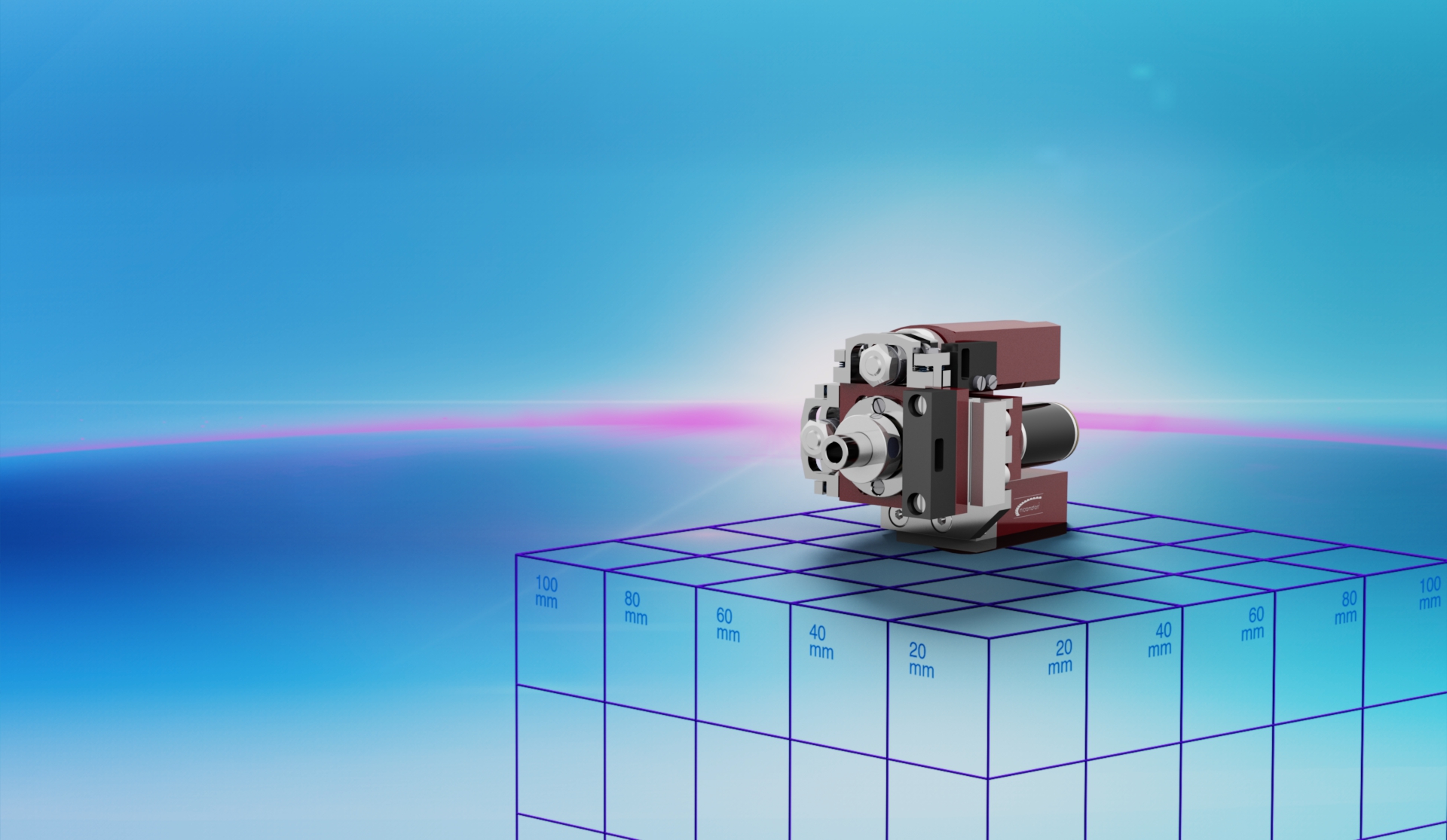
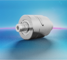
BryleeDrive® HighAcc 36mm – Type 1
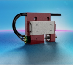
The BryleeDrive® HighAcc 36mm – type 1 micro positioning system combines three degrees of freedom: two linear and one rotary movement.
All three axes of the micro positioning system can easily be operated in an open loop control, as each is driven by stepper motors with 20 steps per rotation.
In addition, the rotative axis is equipped with a hollow shaft. In this way, optical or electrical signals can be guided through the central rotary axis of the gear, thereby saving space.
Zero-backlash MaalonDrive® gears with a reduction ratio of 160:1 or 500:1 form the heart of this multi-axis microsystem.
Benefits
1) Compact build up
2) Hollow shaft thru center of rotational axis
3) Integrated tool fitting
4) Step with in the range of nm
5) 2 linear and 1 rotational degree of freedom
Technical parameters
The values shown are based on calculations and measurement procedures carried out by Micromotion GmbH, which are carried out according to the current state of the art. Our definitions can be found at www.micromotion-drives.com. For further information please contact sales@micromotion.de.
Global system
Nr.
Parameter
Symbol
Value
Properties
P-034
x
P-034:The service life is defined by means of the rated operating point, i.e., rated speed and rated torque, as well as a change of the accuracy characteristics, i.e., unidirectional repeatability, transmission accuracy, lost motion, of less than 10% of the respective catalogue value.
Lifetime for rated operation
500 h
P-056
x
P-056:The weight of the drive without cables and plugs.
Weight
m
109 g
P-057
x
P-057:Minimum permissible temperature at which the drive may be stored or decommissioned without being impaired or destroyed as a result.
Min. permissible ambient temperature (non-operating)
T
-20 °C
P-058
x
P-058:Minimum permissible temperature at which the drive can be operated.
Min. permissible ambient temperature (operating)
T
0 °C
P-059
x
P-059:Maximum permissible temperature at which the drive may be stored or decommissioned without being impaired or destroyed as a result.
Max. permissible ambient temperature (non-operating)
T
80 °C
P-060
x
P-060:Maximum permissible temperature at which the drive can still be operated.
Max. permissible ambient temperature (operating)
T
60 °C
Material information
P-900
x
P-900:At Micromotion GmbH, hazardous materials, which are referred to in EU directive 2011/65/EU, are purchased/used only in compliance with this directive.
RoHS compliant
ja
Axis 1: linear axis for x-direction
Nr.
Parameter
Symbol
Value
Material information
P-003
x
P-003:The reduction ratio describes the relationship between the input movement and the output movement. With a reduction ratio, the output movement is smaller than the input movement.
Ratio
i
500 : 1
P-004
x
P-004:With self-locking, the forces caused by friction are always greater than the applied adjustment forces due to the geometric relationships of the sliding partners. Due to the geometric conditions, the sliding partner in which the force is initiated cannot be moved relative to the sliding parter on which the adjustment force is applied.
Self-locking
ja
P-005
x
P-005:The travel range describes the travel range available for the application.
The travel range characteristic describes the characteristic of the travel range as a function of the angular position of the eccentric. It is defined such that at an angular position of 0 degrees, the eccentric is perpendicular to the resulting movement direction and has no deflection in the adjustment direction.
The max. travel range specifies the maximum available travel range of an eccentric kinematics.
Max. travel range
s
1000 μm
P-016
x
P-016:Rated torque or rated force is defined as the torque or force at which the service life is achieved under rated conditions, i.e., rated speed.
With drive systems, the motor torque may, in some cases, not be adequate for overcoming the running torque of the complete system under rated conditions.
Rated force
F
8 N
P-017
x
P-017:The peak torque or peak force is the loading of the components in the drive train, e.g., the teeth of the gears, still below the fatigue strength.
This does, however, result in increased tooth wear, which leads to a reduction in the service life.
With drive systems, the motor torque may, in some cases, not be adequate for overcoming the running torque of the complete system at peak torque or peak force.
Peak force
F
24 N
P-018
x
P-018:The momentary peak torque or momentary peak force describes the maximum permissible torque or force that can act on the actuator. If the momentary peak torque or momentary peak force is exceeded, damage or a reduced life time of the actuator cannot be ruled out. With momentary peak torque or momentary peak force, the elastic deformations of the teeth are still small enough that no tooth meshing problems occur and proper function is ensured. The loads do, however, exceed the limit of the fatigue strength. Thus, the number of loads should be minimised. Should it occur once, breakage or failure will not result. With drive systems, the motor torque may, in some cases, not be adequate for overcoming the running torque of the complete system at momentary peak torque or momentary peak force. In drive systems, the motor torque may not be sufficient to generate enough torque to meet the permissible momentary peak torque or momentary peak force. On the other hand, in drive systems, the existing motor torque can be so high that the drive system can exceed the permissible momentary peak torque or momentary peak force and the drive system can be damaged.
Momentary peak force
F
32 N
P-035
x
P-035:The backlash can be determined from the course of the hysteresis curve of a gear or mechanical transmission system. The backlash is defined as the range in which the course of the hysteresis curve is vertical, i.e. there is a change in angle or position without changing the torque or force. The hysteresis curve is determined by loading the output with a clockwise and counterclockwise torque or force when the drive is blocked and measuring the associated angular torsion.
Radial backlash output shaft
0 μm
P-036
x
P-036:The backlash can be determined from the course of the hysteresis curve of a gear or mechanical transmission system. The backlash is defined as the range in which the course of the hysteresis curve is vertical, i.e. there is a change in angle or position without changing the torque or force. The hysteresis curve is determined by loading the output with a clockwise and counterclockwise torque or force when the drive is blocked and measuring the associated angular torsion.
Axial backlash output shaft
0 μm
P-037
x
P-037:Stiffness of the bearing in the radial direction, i.e., elastic deflection of the mounted shaft in the radial direction as a function of the applied force.
Radial stiffness
c
2.3 N/μm
P-038
x
P-038:Stiffness of the bearing in the axial direction, i.e., elastic deflection of the mounted shaft in the axial direction as a function of the applied force.
Axial stiffness
c
40 N/μm
P-039
x
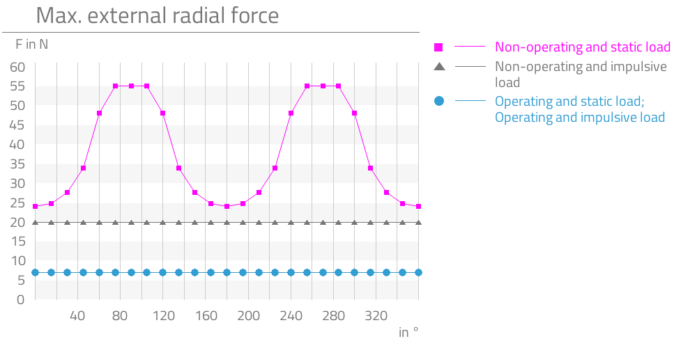
P-039:Max. permissible radial load on the output shaft (not in operation, force applied constantly)
Describes the maximum permissible radial load on the output shaft, whereby the drive is not in operation, i.e., is at a standstill and the force is applied statically. The static load-bearing capacity of the ball bearings Co and the geometric relationships from the point of force application and the bearing distance are decisive for the determination. For the permissible force, the worst case is assumed as the point of force application, i.e., the maximum distance between the ball bearings and the end of the output shaft.
Max. radial load on output shaft (non-operating, constant load)
F
55 N
P-040
x
P-040:Max. permissible radial load on the output shaft (not in operation, force applied impulsively)
Describes the maximum permissible radial load on the output shaft, whereby the drive is not in operation, i.e., is at a standstill and the force is applied impulsively. The load-bearing capacity of the ball bearings is decisive for the determination. With impulsive loading, the permissible load-bearing capacity of the bearings is reduced to one third of Co.
Max. radial load on output shaft (non-operating, impulsive load)
F
20 N
P-041
x
P-041:Max. permissible radial load on the output shaft (in operation, force applied constantly)
Describes the maximum permissible radial load on the output shaft, whereby the drive is in operation and the force is applied statically. Particularly important for the determination of the permissible force in the dynamic case are, in addition to the load-bearing capacity of the ball bearings, the stiffness of the bearing and the run-out error on the dynamic spline caused by elastic deformation. For the permissible force, the worst case is assumed as the point of force application, i.e., the maximum distance between the ball bearings and the end of the output shaft.
Max. radial load on output shaft (operating, constant load)
F
7 N
P-042
x
P-042:Max. permissible radial load on the output shaft (in operation, force applied impulsively)
Describes the maximum permissible radial load on the output shaft, whereby the drive is in operation, i.e., is turning, and the force is applied impulsively. With impulsive loading, the permissible dynamic load-bearing capacity of the ball bearings is reduced to one third of Cr. Likewise decisive for the determination are, in addition to the load-bearing capacity of the ball bearings, the elastic deformation of the output shaft near the dynamic spline and the associated run-out error due to the stiffness of the bearing.
Max. radial load on output shaft (operating, impulsive load)
F
7 N
P-043
x
P-043:Max. permissible axial load on the output shaft (not in operation, force applied constantly)
Describes the maximum permissible axial load on the output shaft, whereby the drive is not in operation, i.e., is at a standstill and the force is applied statically. Decisive for the determination is the static load bearing capacity of the ball bearings as well as the elastic deformation of the output shaft due to the stiffness of the output bearing and the associated position of the dynamic spline.
Max. axial load on output shaft (non-operating, constant
F
150 N
P-044
x
P-044:Max. permissible axial load on the output shaft (not in operation, force applied impulsively)
Describes the maximum permissible axial load on the output shaft, whereby the drive is not in operation, i.e., is at a standstill and the force is applied impulsively. Decisive for the determination is the static load bearing capacity of the ball bearings, which, in the impulsive case, corresponds to just one third of Co, as well as the elastic deformation of the output shaft due to the stiffness of the output bearing and the associated position of the dynamic spline.
Max. axial load on output shaft (non-operating, impulsive load)
F
50 N
P-045
x
P-045:Max. permissible axial load on the output shaft (in operation, force applied constantly)
Describes the maximum permissible axial load on the output shaft, whereby the drive is in operation, i.e., is turning, and the force is applied statically. Decisive for the determination is the dynamic load bearing capacity of the ball bearings as well as the elastic deformation of the output shaft due to the stiffness of the output bearing and the associated position of the dynamic spline.
Max. axial load on output shaft (operating, constant load)
F
380 N
P-046
x
P-046:Max. permissible axial load on the output shaft (in operation, force applied impulsively)
Describes the maximum permissible axial load on the output shaft, whereby the drive is in operation, i.e., is turning, and the force is applied impulsively. Decisive for the determination is the dynamic load bearing capacity of the ball bearings, which, in the impulsive case, corresponds to just one third of Cr, as well as the elastic deformation of the output shaft due to the stiffness of the output bearing and the associated change in position of the dynamic spline.
Max. axial load on output shaft (operating, impulsive load)
F
127 N
P-055
x
P-055:The moment of inertia specifies a body’s resistance to change its rotational movement.
Moment of inertia
I
922 * 10-4 gcm2
Motor data: Stepper AM 1020-2R-A-0.25-8-10/1977
P-100
x
P-100:
Motortype
Stepper
P-102
x
P-102:The maximum speed of the motor describes the speed before mechanical damages occur to the commutator, the rotor or the bearing.
Maximum speed of motor
n
21000 rpm
P-103
x
P-103:Describes the step frequency at which the rotor can experience resonance vibrations while the motor is operated under no load. It is recommended that this frequency be avoided in normal operation and that the motor be started at a higher frequency or that half- or micro-steps be used. Additional inertial masses, e.g., through a gear, reduce the resonance frequency.
Resonance frequency of motor
f
140 Hz
P-105
x
P-105:Describes the torque developed by the motor while at a standstill.
Holding torque of motor (unpowered)
T
0.2 mNm
P-109
x
P-109:The phase current that may flow through both phase coils without the motor overheating while at an ambient temperature of 20°C and constant operation.
Rated current of motor
I
250 mA
P-111
x
P-111:The rated voltage corresponds to the voltage at which all other rated characteristic values of the motor, particularly the rated current at 20°C, are set, measured and classified.
Rated voltage of motor
U
2 V
P-112
x
P-112:The phase resistance describes the ohmic resistance of the coil of a phase at an ambient temperature of 20°C in the steady state.
Phase resistance of motor
R
8 ohm
P-113
x
P-113:Describes the inductance of the coil of a phase at an ambient temperature measured at 1 kHz.
Inductance of motor
L
2.4 mH
P-114
x
P-114:Describes the amplitude of the bemf.
Amplitude BEMF of motor
U
0.6 mV/rpm
P-115
x
P-115:The full step angle of the motor describes the angle at which the rotor turns if a phase is advanced.
Full step angle of motor
18 °
P-116
x
P-116:The angular accuracy of step describes the deviation of the current rotor position from the ideal target rotor position, whereby no external load is applied.
Angular accuracy of step of motor
±1.8 °
P-117
x
P-117:The electrical time constant describes the time required to achieve 67% of the possible phase current of a specified operating point.
Electrical time constant of motor
t
0.32 ms
P-118
x
P-118:The maximum temperature that may occur in the coil without destroying the magnets or the coil.
The coil temperature can be calculated by measuring the change in resistance and the temperature coefficient alpha, which is dependent on the coil wire material. T1 = 1/alpha * (R1/R0 + alpha*T0 – 1)
Max. coil temperature of motor
T
130 °C
P-119
x
P-119:Describes the thermal resistance of the motor between coil and housing.
Thermal resistance of motor between coil and housing
Rth1
3.9 K/W
P-120
x
P-120:Describes the thermal resistance of the motor between housing and ambient air.
Thermal resistance of motor between housing and air
Rth2
53.8 K/W
P-121
x
P-121:Describes the thermal time constant of the motor coil.
Thermal time constant of the coil of the motor
τw1
3200 ms
P-122
x
P-122:Describes the thermal time constant of the motor housing.
Thermal time constant of the housing of the motor
τw2
200000 ms
P-123
x
P-123:Describes the insulation voltage of the motor.
Insulation voltage of motor
U
200 V
Excenter data
P-501
x
P-501:The eccentricity is the distance of the rotary axis of the input shaft to the axis of the eccentric.
Eccentricity
500 μm
P-504
x
P-504:
Max. radial load on eccentric bearing (non-operating, constant load)
F
24 N
P-505
x
P-505:
Max. radial load on eccentric bearing (non-operating, impulsive load)
F
20 N
P-506
x
P-506:For this value, the force application point is seen at the eccentric. Because of the eccentricity and due to the leverage and the radial force occurs a torque on the gear. Thus, at this value, the torque load capacity of the gear as well as the load capacity of the bearing is taken into account at the same time.
Max. radial load on eccentric bearing (operating, constant load)
F
7 N
P-507
x
P-507:
Max. radial load on eccentric bearing (operating, impulsive load)
F
7 N
P-508
x
P-508:
Max. axial load on eccentric bearing (non-operating, constant load)
F
150 N
P-509
x
P-509:
Max. axial load on eccentric bearing (non-operating, impulsive load)
F
50 N
P-510
x
P-510:
Max. axial load on eccentric bearing (operating, constant load)
F
380 N
P-511
x
P-511:
Max. axial load on eccentric bearing (operating, impulsive load)
F
127 N
P-513
x
P-513:
Eccentricity error
20 μm
Data linear bearing
P-600
x
P-600:
Type of guiding system
Micro frictionless table type NDN
P-601
x
P-601:
Max. lateral force in y-direction (non-operating, constant load)
F
50 N
P-602
x
P-602:
Max. lateral force in y-direction (non-operating, impulsive load)
F
50 N
P-603
x
P-603:
Max. lateral force in y-direction (operating, constant load)
F
50 N
P-604
x
P-604:
Max. lateral force in y-direction (operating, impulsive load)
F
50 N
P-605
x
P-605:
Max. lateral force in z-direction (non-operating, constant load)
F
50 N
P-606
x
P-606:
Max. lateral force in z-direction (non-operating, impulsive load)
F
50 N
P-607
x
P-607:
Max. lateral force in z-direction (operating, constant load)
F
50 N
P-608
x
P-608:
Max. lateral force in z-direction (operating, impulsive load)
F
50 N
P-609
x
P-609:
Max. overturning around y-axis (non-operating, constant load)
T
90 mNm
P-610
x
P-610:
Max. overturning around y-axis (non-operating, impulsive load)
T
90 mNm
P-611
x
P-611:
Max. overturning around y-axis (operating, constant load)
T
90 mNm
P-612
x
P-612:
Max. overturning around y-axis (operating, impulsive load)
T
90 mNm
P-613
x
P-613:
Max. overturning around z-axis (non-operating, constant load)
T
140 mNm
P-614
x
P-614:
Max. overturning around z-axis (non-operating, impulsive load)
T
140 mNm
P-615
x
P-615:
Max. overturning around z-axis (operating, constant load)
T
140 mNm
P-616
x
P-616:
Max. overturning around z-axis (operating, impulsive load)
T
140 mNm
P-618
x
P-618:
Stiffness in y-direction
c
10 N/μm
P-619
x
P-619:
Stiffness in z-direction
c
10 N/μm
P-620
x
P-620:
Backlash of linear guiding in y-direction
Zero backlash/ preloaded μm
P-621
x
P-621:
Backlash of linear guiding in z-direction
Zero backlash/ preloaded μm
Material information
P-901
x
P-901:
Lubrication of output bearing gearbox
Longtime PD2
P-903
x
P-903:
Lubrication of gear component set
Molykote BR 2 plus
P-904
x
P-904:
Lubrication of bearing motor
Synthetic light ester oil
P-906
x
P-906:
Lubrication of linear bearing
KP2K/ DIN 51502
P-907
x
P-907:
Lubrication of eccentric bearing
Longtime PD2
P-908
x
P-908:
Material of gear component set
NiFe
P-909
x
P-909:
Material of output bearing gearbox
1.4108 DIN EN
P-911
x
P-911:
Material of bearing motor
Stainless steel
P-912
x
P-912:
Material of gearbox output side
1.4305 DIN EN
P-914
x
P-914:
Material of motor housing
Anodized aluminum
P-915
x
P-915:
Material of eccentric bearing
1.4108 DIN EN
Axis 2: linear axis for y-direction
Nr.
Parameter
Symbol
Value
Material information
P-003
x
P-003:The reduction ratio describes the relationship between the input movement and the output movement. With a reduction ratio, the output movement is smaller than the input movement.
Ratio
i
500 : 1
P-004
x
P-004:With self-locking, the forces caused by friction are always greater than the applied adjustment forces due to the geometric relationships of the sliding partners. Due to the geometric conditions, the sliding partner in which the force is initiated cannot be moved relative to the sliding parter on which the adjustment force is applied.
Self-locking
ja
P-005
x
P-005:The travel range describes the travel range available for the application.
The travel range characteristic describes the characteristic of the travel range as a function of the angular position of the eccentric. It is defined such that at an angular position of 0 degrees, the eccentric is perpendicular to the resulting movement direction and has no deflection in the adjustment direction.
The max. travel range specifies the maximum available travel range of an eccentric kinematics.
Max. travel range
s
1000 μm
P-016
x
P-016:Rated torque or rated force is defined as the torque or force at which the service life is achieved under rated conditions, i.e., rated speed.
With drive systems, the motor torque may, in some cases, not be adequate for overcoming the running torque of the complete system under rated conditions.
Rated force
F
8 N
P-017
x
P-017:The peak torque or peak force is the loading of the components in the drive train, e.g., the teeth of the gears, still below the fatigue strength.
This does, however, result in increased tooth wear, which leads to a reduction in the service life.
With drive systems, the motor torque may, in some cases, not be adequate for overcoming the running torque of the complete system at peak torque or peak force.
Peak force
F
24 N
P-018
x
P-018:The momentary peak torque or momentary peak force describes the maximum permissible torque or force that can act on the actuator. If the momentary peak torque or momentary peak force is exceeded, damage or a reduced life time of the actuator cannot be ruled out. With momentary peak torque or momentary peak force, the elastic deformations of the teeth are still small enough that no tooth meshing problems occur and proper function is ensured. The loads do, however, exceed the limit of the fatigue strength. Thus, the number of loads should be minimised. Should it occur once, breakage or failure will not result. With drive systems, the motor torque may, in some cases, not be adequate for overcoming the running torque of the complete system at momentary peak torque or momentary peak force. In drive systems, the motor torque may not be sufficient to generate enough torque to meet the permissible momentary peak torque or momentary peak force. On the other hand, in drive systems, the existing motor torque can be so high that the drive system can exceed the permissible momentary peak torque or momentary peak force and the drive system can be damaged.
Momentary peak force
F
32 N
P-035
x
P-035:The backlash can be determined from the course of the hysteresis curve of a gear or mechanical transmission system. The backlash is defined as the range in which the course of the hysteresis curve is vertical, i.e. there is a change in angle or position without changing the torque or force. The hysteresis curve is determined by loading the output with a clockwise and counterclockwise torque or force when the drive is blocked and measuring the associated angular torsion.
Radial backlash output shaft
0 μm
P-036
x
P-036:The backlash can be determined from the course of the hysteresis curve of a gear or mechanical transmission system. The backlash is defined as the range in which the course of the hysteresis curve is vertical, i.e. there is a change in angle or position without changing the torque or force. The hysteresis curve is determined by loading the output with a clockwise and counterclockwise torque or force when the drive is blocked and measuring the associated angular torsion.
Axial backlash output shaft
0 μm
P-037
x
P-037:Stiffness of the bearing in the radial direction, i.e., elastic deflection of the mounted shaft in the radial direction as a function of the applied force.
Radial stiffness
c
2.3 N/μm
P-038
x
P-038:Stiffness of the bearing in the axial direction, i.e., elastic deflection of the mounted shaft in the axial direction as a function of the applied force.
Axial stiffness
c
40 N/μm
P-039
x
P-039:Max. permissible radial load on the output shaft (not in operation, force applied constantly)
Describes the maximum permissible radial load on the output shaft, whereby the drive is not in operation, i.e., is at a standstill and the force is applied statically. The static load-bearing capacity of the ball bearings Co and the geometric relationships from the point of force application and the bearing distance are decisive for the determination. For the permissible force, the worst case is assumed as the point of force application, i.e., the maximum distance between the ball bearings and the end of the output shaft.
Max. radial load on output shaft (non-operating, constant load)
F
55 N
P-040
x
P-040:Max. permissible radial load on the output shaft (not in operation, force applied impulsively)
Describes the maximum permissible radial load on the output shaft, whereby the drive is not in operation, i.e., is at a standstill and the force is applied impulsively. The load-bearing capacity of the ball bearings is decisive for the determination. With impulsive loading, the permissible load-bearing capacity of the bearings is reduced to one third of Co.
Max. radial load on output shaft (non-operating, impulsive load)
F
20 N
P-041
x
P-041:Max. permissible radial load on the output shaft (in operation, force applied constantly)
Describes the maximum permissible radial load on the output shaft, whereby the drive is in operation and the force is applied statically. Particularly important for the determination of the permissible force in the dynamic case are, in addition to the load-bearing capacity of the ball bearings, the stiffness of the bearing and the run-out error on the dynamic spline caused by elastic deformation. For the permissible force, the worst case is assumed as the point of force application, i.e., the maximum distance between the ball bearings and the end of the output shaft.
Max. radial load on output shaft (operating, constant load)
F
7 N
P-042
x
P-042:Max. permissible radial load on the output shaft (in operation, force applied impulsively)
Describes the maximum permissible radial load on the output shaft, whereby the drive is in operation, i.e., is turning, and the force is applied impulsively. With impulsive loading, the permissible dynamic load-bearing capacity of the ball bearings is reduced to one third of Cr. Likewise decisive for the determination are, in addition to the load-bearing capacity of the ball bearings, the elastic deformation of the output shaft near the dynamic spline and the associated run-out error due to the stiffness of the bearing.
Max. radial load on output shaft (operating, impulsive load)
F
7 N
P-043
x
P-043:Max. permissible axial load on the output shaft (not in operation, force applied constantly)
Describes the maximum permissible axial load on the output shaft, whereby the drive is not in operation, i.e., is at a standstill and the force is applied statically. Decisive for the determination is the static load bearing capacity of the ball bearings as well as the elastic deformation of the output shaft due to the stiffness of the output bearing and the associated position of the dynamic spline.
Max. axial load on output shaft (non-operating, constant
F
150 N
P-044
x
P-044:Max. permissible axial load on the output shaft (not in operation, force applied impulsively)
Describes the maximum permissible axial load on the output shaft, whereby the drive is not in operation, i.e., is at a standstill and the force is applied impulsively. Decisive for the determination is the static load bearing capacity of the ball bearings, which, in the impulsive case, corresponds to just one third of Co, as well as the elastic deformation of the output shaft due to the stiffness of the output bearing and the associated position of the dynamic spline.
Max. axial load on output shaft (non-operating, impulsive load)
F
50 N
P-045
x
P-045:Max. permissible axial load on the output shaft (in operation, force applied constantly)
Describes the maximum permissible axial load on the output shaft, whereby the drive is in operation, i.e., is turning, and the force is applied statically. Decisive for the determination is the dynamic load bearing capacity of the ball bearings as well as the elastic deformation of the output shaft due to the stiffness of the output bearing and the associated position of the dynamic spline.
Max. axial load on output shaft (operating, constant load)
F
380 N
P-046
x
P-046:Max. permissible axial load on the output shaft (in operation, force applied impulsively)
Describes the maximum permissible axial load on the output shaft, whereby the drive is in operation, i.e., is turning, and the force is applied impulsively. Decisive for the determination is the dynamic load bearing capacity of the ball bearings, which, in the impulsive case, corresponds to just one third of Cr, as well as the elastic deformation of the output shaft due to the stiffness of the output bearing and the associated change in position of the dynamic spline.
Max. axial load on output shaft (operating, impulsive load)
F
127 N
P-055
x
P-055:The moment of inertia specifies a body’s resistance to change its rotational movement.
Moment of inertia
I
922 * 10-4 gcm2
Motor data: Stepper AM 1020-2R-A-0.25-8-10/1977
P-100
x
P-100:
Motortype
Stepper
P-102
x
P-102:The maximum speed of the motor describes the speed before mechanical damages occur to the commutator, the rotor or the bearing.
Maximum speed of motor
n
21000 rpm
P-103
x
P-103:Describes the step frequency at which the rotor can experience resonance vibrations while the motor is operated under no load. It is recommended that this frequency be avoided in normal operation and that the motor be started at a higher frequency or that half- or micro-steps be used. Additional inertial masses, e.g., through a gear, reduce the resonance frequency.
Resonance frequency of motor
f
140 Hz
P-105
x
P-105:Describes the torque developed by the motor while at a standstill.
Holding torque of motor (unpowered)
T
0.2 mNm
P-109
x
P-109:The phase current that may flow through both phase coils without the motor overheating while at an ambient temperature of 20°C and constant operation.
Rated current of motor
I
250 mA
P-111
x
P-111:The rated voltage corresponds to the voltage at which all other rated characteristic values of the motor, particularly the rated current at 20°C, are set, measured and classified.
Rated voltage of motor
U
2 V
P-112
x
P-112:The phase resistance describes the ohmic resistance of the coil of a phase at an ambient temperature of 20°C in the steady state.
Phase resistance of motor
R
8 ohm
P-113
x
P-113:Describes the inductance of the coil of a phase at an ambient temperature measured at 1 kHz.
Inductance of motor
L
2.4 mH
P-114
x
P-114:Describes the amplitude of the bemf.
Amplitude BEMF of motor
U
0.6 mV/rpm
P-115
x
P-115:The full step angle of the motor describes the angle at which the rotor turns if a phase is advanced.
Full step angle of motor
18 °
P-116
x
P-116:The angular accuracy of step describes the deviation of the current rotor position from the ideal target rotor position, whereby no external load is applied.
Angular accuracy of step of motor
±1.8 °
P-117
x
P-117:The electrical time constant describes the time required to achieve 67% of the possible phase current of a specified operating point.
Electrical time constant of motor
t
0.32 ms
P-118
x
P-118:The maximum temperature that may occur in the coil without destroying the magnets or the coil.
The coil temperature can be calculated by measuring the change in resistance and the temperature coefficient alpha, which is dependent on the coil wire material. T1 = 1/alpha * (R1/R0 + alpha*T0 – 1)
Max. coil temperature of motor
T
130 °C
P-119
x
P-119:Describes the thermal resistance of the motor between coil and housing.
Thermal resistance of motor between coil and housing
Rth1
3.9 K/W
P-120
x
P-120:Describes the thermal resistance of the motor between housing and ambient air.
Thermal resistance of motor between housing and air
Rth2
53.8 K/W
P-121
x
P-121:Describes the thermal time constant of the motor coil.
Thermal time constant of the coil of the motor
τw1
3200 ms
P-122
x
P-122:Describes the thermal time constant of the motor housing.
Thermal time constant of the housing of the motor
τw2
200000 ms
P-123
x
P-123:Describes the insulation voltage of the motor.
Insulation voltage of motor
U
200 V
Excenter data
P-501
x
P-501:The eccentricity is the distance of the rotary axis of the input shaft to the axis of the eccentric.
Eccentricity
500 μm
P-504
x
P-504:
Max. radial load on eccentric bearing (non-operating, constant load)
F
24 N
P-505
x
P-505:
Max. radial load on eccentric bearing (non-operating, impulsive load)
F
20 N
P-506
x
P-506:For this value, the force application point is seen at the eccentric. Because of the eccentricity and due to the leverage and the radial force occurs a torque on the gear. Thus, at this value, the torque load capacity of the gear as well as the load capacity of the bearing is taken into account at the same time.
Max. radial load on eccentric bearing (operating, constant load)
F
7 N
P-507
x
P-507:
Max. radial load on eccentric bearing (operating, impulsive load)
F
7 N
P-508
x
P-508:
Max. axial load on eccentric bearing (non-operating, constant load)
F
150 N
P-509
x
P-509:
Max. axial load on eccentric bearing (non-operating, impulsive load)
F
50 N
P-510
x
P-510:
Max. axial load on eccentric bearing (operating, constant load)
F
380 N
P-511
x
P-511:
Max. axial load on eccentric bearing (operating, impulsive load)
F
127 N
P-513
x
P-513:
Eccentricity error
20 μm
Data linear bearing
P-600
x
P-600:
Type of guiding system
Micro frictionless table type NDN
P-601
x
P-601:
Max. lateral force in y-direction (non-operating, constant load)
F
50 N
P-602
x
P-602:
Max. lateral force in y-direction (non-operating, impulsive load)
F
50 N
P-603
x
P-603:
Max. lateral force in y-direction (operating, constant load)
F
50 N
P-604
x
P-604:
Max. lateral force in y-direction (operating, impulsive load)
F
50 N
P-605
x
P-605:
Max. lateral force in z-direction (non-operating, constant load)
F
50 N
P-606
x
P-606:
Max. lateral force in z-direction (non-operating, impulsive load)
F
50 N
P-607
x
P-607:
Max. lateral force in z-direction (operating, constant load)
F
50 N
P-608
x
P-608:
Max. lateral force in z-direction (operating, impulsive load)
F
50 N
P-609
x
P-609:
Max. overturning around y-axis (non-operating, constant load)
T
90 mNm
P-610
x
P-610:
Max. overturning around y-axis (non-operating, impulsive load)
T
90 mNm
P-611
x
P-611:
Max. overturning around y-axis (operating, constant load)
T
90 mNm
P-612
x
P-612:
Max. overturning around y-axis (operating, impulsive load)
T
90 mNm
P-613
x
P-613:
Max. overturning around z-axis (non-operating, constant load)
T
140 mNm
P-614
x
P-614:
Max. overturning around z-axis (non-operating, impulsive load)
T
140 mNm
P-615
x
P-615:
Max. overturning around z-axis (operating, constant load)
T
140 mNm
P-616
x
P-616:
Max. overturning around z-axis (operating, impulsive load)
T
140 mNm
P-618
x
P-618:
Stiffness in y-direction
c
10 N/μm
P-619
x
P-619:
Stiffness in z-direction
c
10 N/μm
P-620
x
P-620:
Backlash of linear guiding in y-direction
Zero backlash/ preloaded μm
P-621
x
P-621:
Backlash of linear guiding in z-direction
Zero backlash/ preloaded μm
Material information
P-901
x
P-901:
Lubrication of output bearing gearbox
Longtime PD2
P-903
x
P-903:
Lubrication of gear component set
Molykote BR 2 plus
P-904
x
P-904:
Lubrication of bearing motor
Synthetic light ester oil
P-906
x
P-906:
Lubrication of linear bearing
KP2K/ DIN 51502
P-907
x
P-907:
Lubrication of eccentric bearing
Longtime PD2
P-908
x
P-908:
Material of gear component set
NiFe
P-909
x
P-909:
Material of output bearing gearbox
1.4108 DIN EN
P-911
x
P-911:
Material of bearing motor
Stainless steel
P-912
x
P-912:
Material of gearbox output side
1.4305 DIN EN
P-914
x
P-914:
Material of motor housing
Anodized aluminum
P-915
x
P-915:
Material of eccentric bearing
1.4108 DIN EN
Axis 3: rotational axis with hollow shaft
Nr.
Parameter
Symbol
Value
Material information
P-003
x
P-003:The reduction ratio describes the relationship between the input movement and the output movement. With a reduction ratio, the output movement is smaller than the input movement.
Ratio
i
210 : 1
P-004
x
P-004:With self-locking, the forces caused by friction are always greater than the applied adjustment forces due to the geometric relationships of the sliding partners. Due to the geometric conditions, the sliding partner in which the force is initiated cannot be moved relative to the sliding parter on which the adjustment force is applied.
Self-locking
ja
P-006
x
P-006:Refers to the smallest diameter that is available to the application on the central rotary axis of the entire drive train.
Hollow shaft
ja
P-008
x
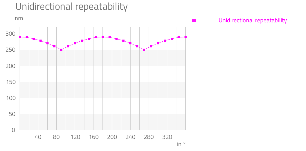
P-008:The unidirectional repeatability describes the positional uncertainty that arises when repeatedly approaching a setpoint from the same direction with no load.
The repeatability is defined as half of the maximum difference together with a +/- sign.
Repeatability unidirectional
30.4286 arcsec
P-009
x
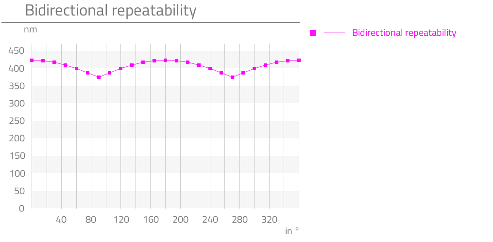
P-009:The bidirectional repeatability describes the positional uncertainty that arises when repeatedly approaching a setpoint from the opposite direction with no load.
The repeatability is defined as half of the maximum difference together with a +/- sign.
Repeatability bidirectional
20.5143 arcmin
P-010
x
P-010:The positioning accuracy of a gear describes the maximum deviation of the output angle relative to the setpoint or, with a linear actuator, the maximum deviation of the output position relative to the setpoint.
The measurement is performed during a complete rotation of the output element or a complete traverse of the travel range path with the aid of a high-resolution measurement system.
There is no change in the direction of rotation or direction reversal.
The positioning accuracy is defined as the absolute value of the maximum difference between the theoretical setpoint position and the measured actual position of the output element.
Accuracy
13.0286 arcmin
P-011
x
P-011:The transmission accuracy of a gear describes the linearity error between input and output angle.
The measurement is performed during a complete rotation of the output element with the aid of a high-resolution measurement system.
There is no change in the direction of rotation.
The transmission accuracy is defined as the sum of the absolute values of the maximum positive and negative deviation between the theoretical and the measured angular position of the output shaft.
Transmission accuracy
26.0571 arcmin
P-012
x
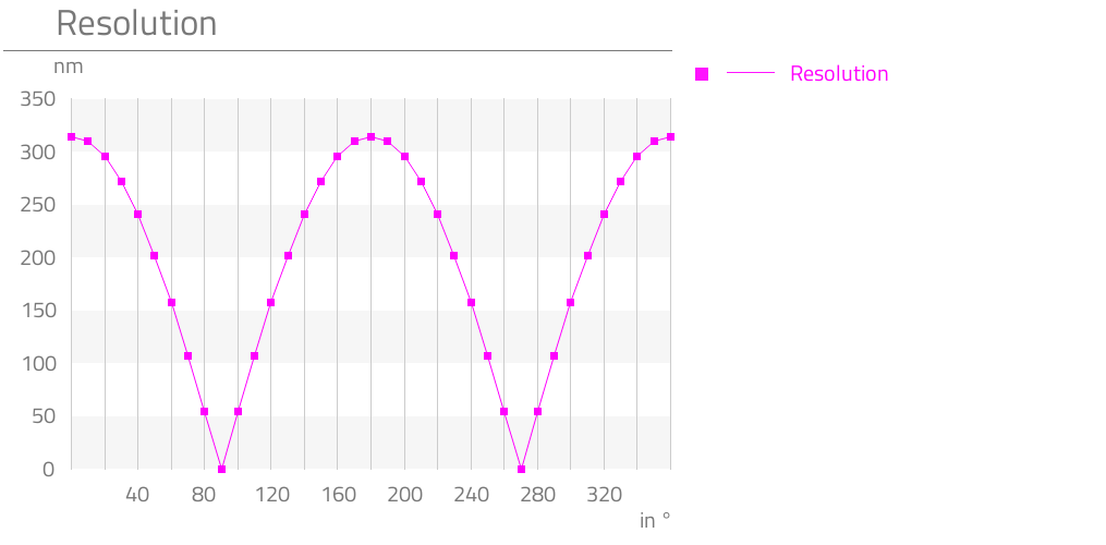
P-012:The positioning resolution refers to the smallest angular change or positional change that can be distinguished by the positioning system.
With eccentric systems, the characteristic of the linearly resulting positioning resolution is described as a function of the angular position and thereby indicates the smallest positional change as a function of the angular position that can be distinguished by the positioning system.
With eccentric systems, it is defined such that at an angular position of 0 degrees, the eccentric is perpendicular to the resulting movement direction.
Resolution
0.0857 °
P-013
x
P-013:The torsional stiffness can be ascertained from the characteristic of the hysteresis curve of a gear.
The torsional stiffness is defined as the slope of the hysteresis line and describes the elastic torsional angle of the output shaft as a function of a torque.
The hysteresis curve is determined by subjecting the output to load while the input is blocked with a clockwise and an anticlockwise torque and the corresponding angular displacement measured.
Torsional stiffness
8.25 Nm/rad
P-014
x
P-014:The value for the lost motion can be ascertained from the characteristic of the hysteresis curve of a gear or linear actuator.
Lost motion is defined as the angular difference or position difference at which the two branches of the hysteresis curve cross the torque or force zero point, i.e., no load is applied.
The hysteresis curve is determined by subjecting the output to load while the input is blocked with a clockwise and an anticlockwise torque or a forward-acting and a backward-acting force and the corresponding angular displacement or positional change measured.
Lost motion
12 arcmin
P-015
x
P-015:The backlash can be determined from the course of the hysteresis curve of a gear or mechanical transmission system. The backlash is defined as the range in which the course of the hysteresis curve is vertical, i.e. there is a change in angle or position without changing the torque or force. The hysteresis curve is determined by loading the output with a clockwise and counterclockwise torque or force when the drive is blocked and measuring the associated angular torsion.
Backlash
0 arcmin
P-016
x
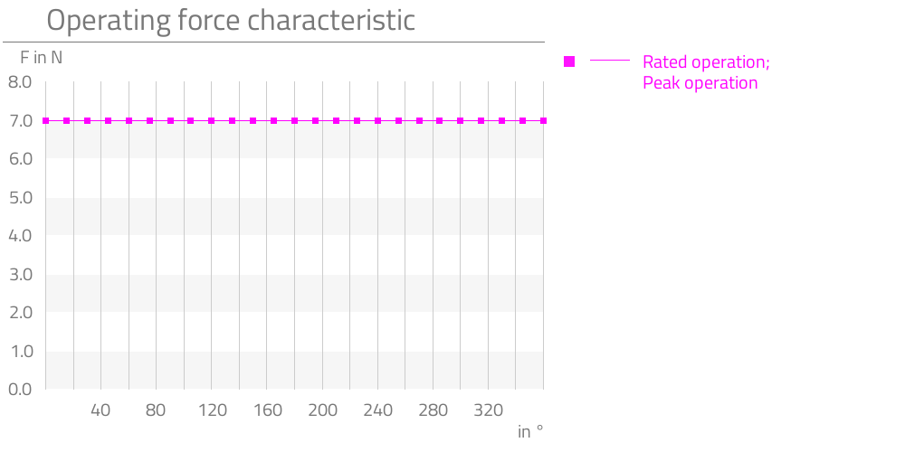
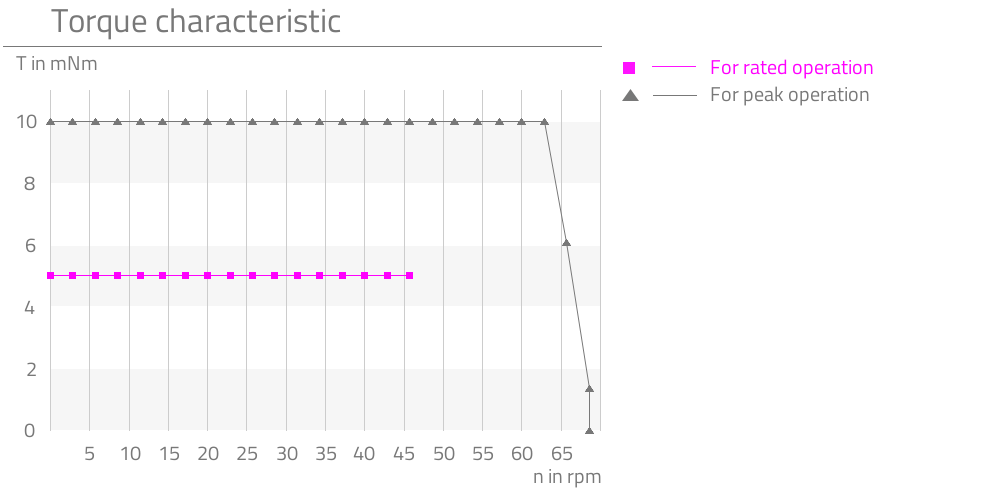
P-016:Rated torque or rated force is defined as the torque or force at which the service life is achieved under rated conditions, i.e., rated speed.
With drive systems, the motor torque may, in some cases, not be adequate for overcoming the running torque of the complete system under rated conditions.
Rated torque
T
5 mNm
P-017
x
P-017:The peak torque or peak force is the loading of the components in the drive train, e.g., the teeth of the gears, still below the fatigue strength.
This does, however, result in increased tooth wear, which leads to a reduction in the service life.
With drive systems, the motor torque may, in some cases, not be adequate for overcoming the running torque of the complete system at peak torque or peak force.
Peak torque
T
10 mNm
P-018
x
P-018:The momentary peak torque or momentary peak force describes the maximum permissible torque or force that can act on the actuator. If the momentary peak torque or momentary peak force is exceeded, damage or a reduced life time of the actuator cannot be ruled out. With momentary peak torque or momentary peak force, the elastic deformations of the teeth are still small enough that no tooth meshing problems occur and proper function is ensured. The loads do, however, exceed the limit of the fatigue strength. Thus, the number of loads should be minimised. Should it occur once, breakage or failure will not result. With drive systems, the motor torque may, in some cases, not be adequate for overcoming the running torque of the complete system at momentary peak torque or momentary peak force. In drive systems, the motor torque may not be sufficient to generate enough torque to meet the permissible momentary peak torque or momentary peak force. On the other hand, in drive systems, the existing motor torque can be so high that the drive system can exceed the permissible momentary peak torque or momentary peak force and the drive system can be damaged.
Momentary peak torque
T
23 mNm
P-021
x
P-021:Rated input speed is defined as the speed at which the service life is achieved under rated conditions, i.e., rated torque.
With drive systems, the motor torque may, in some cases, not be adequate for overcoming the running torque of the complete system at rated speed.
Rated input speed
n
10000 rpm
P-022
x
P-022:The maximum input speed refers to the speed before which mechanical damages occur to components in the drive train, e.g., scoring of the teeth or damage to the ball bearings.
With drive systems, the motor torque may, in some cases, not be adequate for overcoming the running torque of the complete system at maximum speed.
Maximum input speed
n
21000 rpm
P-023
x
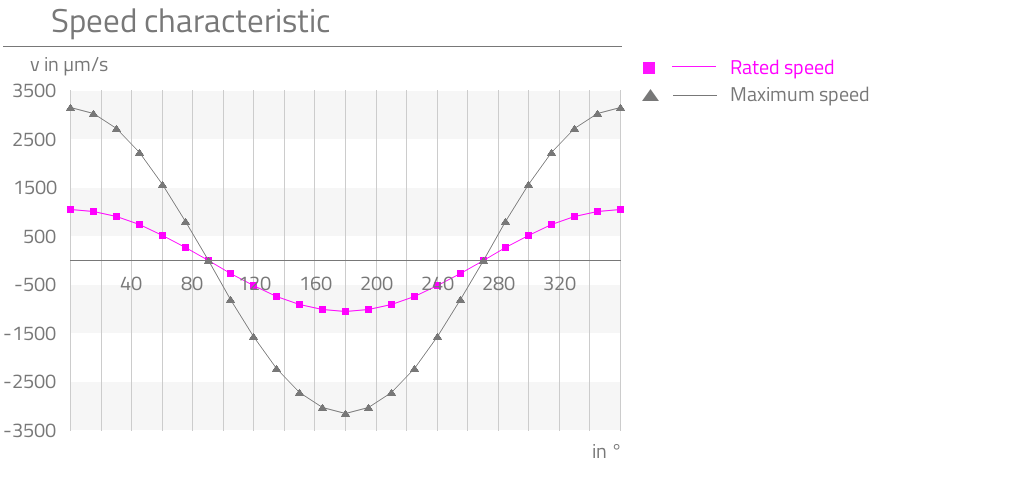
P-023:Rated output speed or rated speed is defined as the speed at which the service life is achieved under rated conditions, i.e., rated torque or rated force.
With drive systems, the motor torque may, in some cases, not be adequate for overcoming the running torque of the complete system at rated speed.
Rated output speed
n
47.619 rpm
P-024
x
P-024:The maximum output speed or maximum speed refers to the speed before which mechanical damages occur to components in the drive train, e.g., scoring of the teeth.
With drive systems, the motor torque may, in some cases, not be adequate for overcoming the running torque of the complete system at maximum speed.
Maximum output speed
n
100 rpm
P-026
x
P-026:The no-load starting torque describes the torque necessary for putting the gear into rotary motion without additional output-side load at 20°C and standard lubricant.
No-load starting torque
T
75 μNm
P-027
x
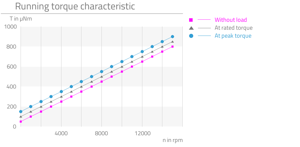
P-027:The running torque describes the torque necessary for driving the gear without additional output-side load at 20°C and standard lubricant at constant speed.
No-load running torque
T
50 μNm
P-028
x
P-028:The rated running torque describes the input-side torque that is required to operate the gear in rated operation, i.e., at rated torque and rated speed.
Rated running torque
T
600 μNm
P-035
x
P-035:The backlash can be determined from the course of the hysteresis curve of a gear or mechanical transmission system. The backlash is defined as the range in which the course of the hysteresis curve is vertical, i.e. there is a change in angle or position without changing the torque or force. The hysteresis curve is determined by loading the output with a clockwise and counterclockwise torque or force when the drive is blocked and measuring the associated angular torsion.
Radial backlash output shaft
0 μm
P-036
x
P-036:The backlash can be determined from the course of the hysteresis curve of a gear or mechanical transmission system. The backlash is defined as the range in which the course of the hysteresis curve is vertical, i.e. there is a change in angle or position without changing the torque or force. The hysteresis curve is determined by loading the output with a clockwise and counterclockwise torque or force when the drive is blocked and measuring the associated angular torsion.
Axial backlash output shaft
0 μm
P-037
x
P-037:Stiffness of the bearing in the radial direction, i.e., elastic deflection of the mounted shaft in the radial direction as a function of the applied force.
Radial stiffness
c
0.48 N/μm
P-038
x
P-038:Stiffness of the bearing in the axial direction, i.e., elastic deflection of the mounted shaft in the axial direction as a function of the applied force.
Axial stiffness
c
10 N/μm
P-039
x
P-039:Max. permissible radial load on the output shaft (not in operation, force applied constantly)
Describes the maximum permissible radial load on the output shaft, whereby the drive is not in operation, i.e., is at a standstill and the force is applied statically. The static load-bearing capacity of the ball bearings Co and the geometric relationships from the point of force application and the bearing distance are decisive for the determination. For the permissible force, the worst case is assumed as the point of force application, i.e., the maximum distance between the ball bearings and the end of the output shaft.
Max. radial load on output shaft (non-operating, constant load)
F
10 N
P-040
x
P-040:Max. permissible radial load on the output shaft (not in operation, force applied impulsively)
Describes the maximum permissible radial load on the output shaft, whereby the drive is not in operation, i.e., is at a standstill and the force is applied impulsively. The load-bearing capacity of the ball bearings is decisive for the determination. With impulsive loading, the permissible load-bearing capacity of the bearings is reduced to one third of Co.
Max. radial load on output shaft (non-operating, impulsive load)
F
5 N
P-041
x
P-041:Max. permissible radial load on the output shaft (in operation, force applied constantly)
Describes the maximum permissible radial load on the output shaft, whereby the drive is in operation and the force is applied statically. Particularly important for the determination of the permissible force in the dynamic case are, in addition to the load-bearing capacity of the ball bearings, the stiffness of the bearing and the run-out error on the dynamic spline caused by elastic deformation. For the permissible force, the worst case is assumed as the point of force application, i.e., the maximum distance between the ball bearings and the end of the output shaft.
Max. radial load on output shaft (operating, constant load)
F
2 N
P-042
x
P-042:Max. permissible radial load on the output shaft (in operation, force applied impulsively)
Describes the maximum permissible radial load on the output shaft, whereby the drive is in operation, i.e., is turning, and the force is applied impulsively. With impulsive loading, the permissible dynamic load-bearing capacity of the ball bearings is reduced to one third of Cr. Likewise decisive for the determination are, in addition to the load-bearing capacity of the ball bearings, the elastic deformation of the output shaft near the dynamic spline and the associated run-out error due to the stiffness of the bearing.
Max. radial load on output shaft (operating, impulsive load)
F
2 N
P-043
x
P-043:Max. permissible axial load on the output shaft (not in operation, force applied constantly)
Describes the maximum permissible axial load on the output shaft, whereby the drive is not in operation, i.e., is at a standstill and the force is applied statically. Decisive for the determination is the static load bearing capacity of the ball bearings as well as the elastic deformation of the output shaft due to the stiffness of the output bearing and the associated position of the dynamic spline.
Max. axial load on output shaft (non-operating, constant
F
30 N
P-044
x
P-044:Max. permissible axial load on the output shaft (not in operation, force applied impulsively)
Describes the maximum permissible axial load on the output shaft, whereby the drive is not in operation, i.e., is at a standstill and the force is applied impulsively. Decisive for the determination is the static load bearing capacity of the ball bearings, which, in the impulsive case, corresponds to just one third of Co, as well as the elastic deformation of the output shaft due to the stiffness of the output bearing and the associated position of the dynamic spline.
Max. axial load on output shaft (non-operating, impulsive load)
F
10 N
P-045
x
P-045:Max. permissible axial load on the output shaft (in operation, force applied constantly)
Describes the maximum permissible axial load on the output shaft, whereby the drive is in operation, i.e., is turning, and the force is applied statically. Decisive for the determination is the dynamic load bearing capacity of the ball bearings as well as the elastic deformation of the output shaft due to the stiffness of the output bearing and the associated position of the dynamic spline.
Max. axial load on output shaft (operating, constant load)
F
100 N
P-046
x
P-046:Max. permissible axial load on the output shaft (in operation, force applied impulsively)
Describes the maximum permissible axial load on the output shaft, whereby the drive is in operation, i.e., is turning, and the force is applied impulsively. Decisive for the determination is the dynamic load bearing capacity of the ball bearings, which, in the impulsive case, corresponds to just one third of Cr, as well as the elastic deformation of the output shaft due to the stiffness of the output bearing and the associated change in position of the dynamic spline.
Max. axial load on output shaft (operating, impulsive load)
F
38 N
P-055
x
P-055:The moment of inertia specifies a body’s resistance to change its rotational movement.
Moment of inertia
I
923 * 10-4 gcm2
Motor data: Stepper AM 1020-2R-A-0.25-8-10/1977
P-100
x
P-100:
Motortype
Stepper
P-102
x
P-102:The maximum speed of the motor describes the speed before mechanical damages occur to the commutator, the rotor or the bearing.
Maximum speed of motor
n
21000 rpm
P-103
x
P-103:Describes the step frequency at which the rotor can experience resonance vibrations while the motor is operated under no load. It is recommended that this frequency be avoided in normal operation and that the motor be started at a higher frequency or that half- or micro-steps be used. Additional inertial masses, e.g., through a gear, reduce the resonance frequency.
Resonance frequency of motor
f
140 Hz
P-105
x
P-105:Describes the torque developed by the motor while at a standstill.
Holding torque of motor (unpowered)
T
0.2 mNm
P-109
x
P-109:The phase current that may flow through both phase coils without the motor overheating while at an ambient temperature of 20°C and constant operation.
Rated current of motor
I
250 mA
P-111
x
P-111:The rated voltage corresponds to the voltage at which all other rated characteristic values of the motor, particularly the rated current at 20°C, are set, measured and classified.
Rated voltage of motor
U
2 V
P-112
x
P-112:The phase resistance describes the ohmic resistance of the coil of a phase at an ambient temperature of 20°C in the steady state.
Phase resistance of motor
R
8 ohm
P-113
x
P-113:Describes the inductance of the coil of a phase at an ambient temperature measured at 1 kHz.
Inductance of motor
L
2.4 mH
P-114
x
P-114:Describes the amplitude of the bemf.
Amplitude BEMF of motor
U
0.6 mV/rpm
P-115
x
P-115:The full step angle of the motor describes the angle at which the rotor turns if a phase is advanced.
Full step angle of motor
18 °
P-116
x
P-116:The angular accuracy of step describes the deviation of the current rotor position from the ideal target rotor position, whereby no external load is applied.
Angular accuracy of step of motor
±1.8 °
P-117
x
P-117:The electrical time constant describes the time required to achieve 67% of the possible phase current of a specified operating point.
Electrical time constant of motor
t
0.32 ms
P-118
x
P-118:The maximum temperature that may occur in the coil without destroying the magnets or the coil.
The coil temperature can be calculated by measuring the change in resistance and the temperature coefficient alpha, which is dependent on the coil wire material. T1 = 1/alpha * (R1/R0 + alpha*T0 – 1)
Max. coil temperature of motor
T
130 °C
P-119
x
P-119:Describes the thermal resistance of the motor between coil and housing.
Thermal resistance of motor between coil and housing
Rth1
3.9 K/W
P-120
x
P-120:Describes the thermal resistance of the motor between housing and ambient air.
Thermal resistance of motor between housing and air
Rth2
53.8 K/W
P-121
x
P-121:Describes the thermal time constant of the motor coil.
Thermal time constant of the coil of the motor
τw1
3200 ms
P-122
x
P-122:Describes the thermal time constant of the motor housing.
Thermal time constant of the housing of the motor
τw2
200000 ms
P-123
x
P-123:Describes the insulation voltage of the motor.
Insulation voltage of motor
U
200 V
Material information
P-901
x
P-901:
Lubrication of output bearing gearbox
Longtime PD2
P-903
x
P-903:
Lubrication of gear component set
Molykote BR 2 plus
P-904
x
P-904:
Lubrication of bearing motor
Synthetic light ester oil
P-908
x
P-908:
Material of gear component set
NiFe
P-909
x
P-909:
Material of output bearing gearbox
1.4108 DIN EN
P-911
x
P-911:
Material of bearing motor
Stainless steel
P-912
x
P-912:
Material of gearbox output side
1.4305 DIN EN
P-914
x
P-914:
Material of motor housing
Anodized aluminum
Graphs
P-008
P-029
P-009
P-012
P-012
P-016
P-502
P-512
P-005

P-016
P-502
P-512
P-005
P-019
P-009
P-008
Alternative products

High repeatability
Lifetime lubrication
Use of high quality materials
Preloaded ball bearing
Zero backlash with optimised fit between speed and resolution

Dry lubrication due to coatings
Use of high quality materials
Simple integration to the application
Robust control without feedback system
Ball screw
Fast delivery
High repeatability
Hollow shaft thru center of rotational axis
Preloaded ball bearing
Zero backlash with optimised fit between speed and transmission ratio

Flexible integration
Vacuum suitable lubrication
Easy controllability
High adjustment speed
Ball screw
Flexible integration
Preloaded ball bearing
Easy controllability
Zero backlash at high adjustment speed
Ball screw

High reliability
Extreme dynamic
Preloaded ball bearing
Robust control without feedback system
High speed
Vacuum suitable lubrication
Robust control without feedback system
Custom designed housing
Integrated limit switches
Ball screw
Flexible integration
Vacuum suitable lubrication
Easy controllability
Ball screw
Zero backlash with speed optimised transmittion ratio